- -10%


Stock map with performance gain: 14-20 HP, 17-21 ft-lb
Phase map 1 with performance gain*: 25-28 hp, 20-23 ft-lb
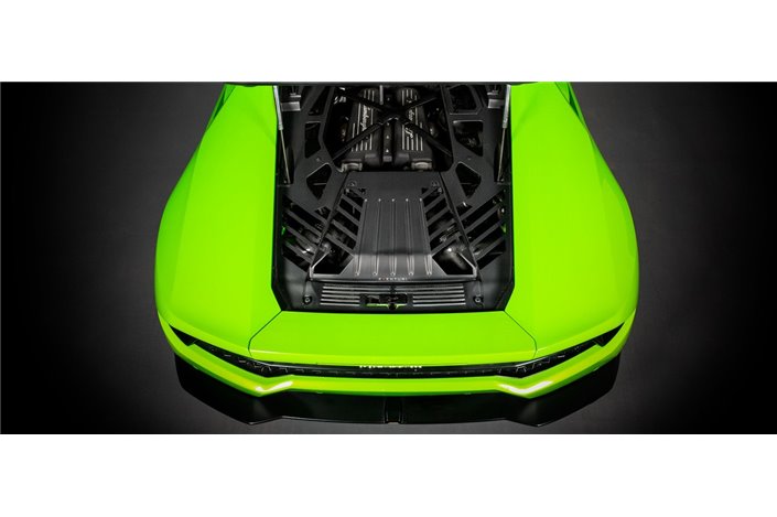
Equipment: 2020+ RSQ8/SQ7/SQ8, 2019+ Urus, 2020+ Cayenne Turbo, 2019+ Bentayga
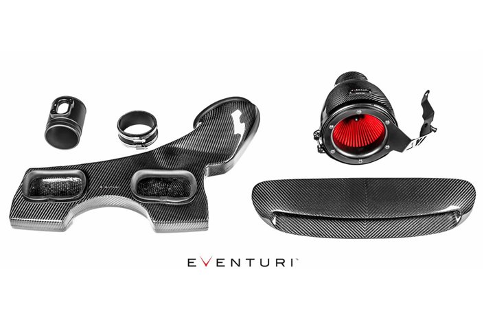
Our naturally aspirated 4.0TFSI V8 The EA825 is a complete redesign and optimization of the entire air intake path. Every component, including the cover, has been developed to allow the twin V8 turbochargers to draw air with less resistance, resulting in industry-leading performance gains. .
*Measured gains may vary based on different ECU settings.
Stock map with performance gain: 14-20 HP, 17-21 ft-lb
Phase map 1 with performance gain*: 25-28 hp, 20-23 ft-lb
Equipment: 2020+ RSQ8/SQ7/SQ8, 2019+ Urus, 2020+ Cayenne Turbo, 2019+ Bentayga
Our naturally aspirated 4.0TFSI V8 The EA825 is a complete redesign and optimization of the entire air intake path. Every component, including the cover, has been developed to allow the twin V8 turbochargers to draw air with less resistance, resulting in industry-leading performance gains. .
*Measured gains may vary based on different ECU settings.

![]()
![]()
![]()
![]()
![]()
![]()
![]()
![]()
![]()
![]()
![]()
![]()
![]()
![]()
The stock airbox cover creates a restriction on the size of the flow manifold that feeds the intakes from the filters. So we increased the height of the center section of the cover to allow for a larger flow manifold and larger cone filters. This removes the inherent restriction and sets our intake apart from the rest of the field who, using the stock cover, must also use a restricted manifold and filter media. The turbo intakes are up to 43% larger in cross-section than stock and are designed with an advanced dimpled internal surface to reduce frictional losses between the flow and the wall boundary. By allowing a "cushion" of air on the wall surface, airflow is able to move through the intakes at higher flow rates with reduced pressure loss. This allows the turbochargers to draw in air with less resistance and therefore reduce the duty cycle of the wastegate, resulting in increased overall performance.
Dynamometer Testing
This intake was independently dyno tested by Eurocharged Canada. Back-to-back tests were performed against the stock airbox and several runs were performed with each setup. The dyno results show a consistent gain throughout the RPM range which can be attributed to the turbos peaking at boost sooner and having a lower wastegate duty cycle due to the increased efficiency of the intake system. The first graph shows the results on a completely stock vehicle with only the intake modified between runs. The second graph shows an RSQ8 that had a stage 1 tune and a drop-in filter as a baseline test. Then the intake was modified leaving the tune as is. The performance gains on both vehicles translate on the road into greater response at half and full throttle with the car pulling much more eagerly towards the redline.
The Eventuri 4.0TFSI V8 intake system is made up of a series of components designed to perform a specific purpose and manufactured to the highest standards. We use 100% pre-preg carbon fiber with no fiberglass, which means we can achieve a smooth internal surface to maintain smoother airflow. Here are the details for each component and the design ethic behind them:
Each intake system consists of:
ENLARGED AIRBOX COVER
The first constraint we had to overcome to dramatically increase the overall intake volume was the airbox cover. The stock cover leaves a shallow opening for the flow manifold and also limits the filtering media used. By creating a raised portion in the center of the cover we are able to create more room for a larger flow manifold and also larger filters. The cover is made from pre-preg carbon fiber and uses the same mounting points as the stock cover.
CARBON FLOW MANIFOLD AND FILTER The manifold
flow duct directs airflow from the filters into the turbo intakes. The stock one is small in size due to the stock cover, but by removing that restriction, we were able to dramatically increase the volume of our version. Additionally, this also gave us the freedom to replace the stock filter with higher flow cone filters that also have a greater total surface area.
TURBO INTAKES
The biggest restriction in the stock system they are the turbo air intakes. The stock intakes are not only small in size, but they also have 2 flex sections. The flex section immediately in front of the turbo creates turbulence as the engine revs. To combat this, the stock intakes also have flow guides at the outlet of the intakes, but these also create restriction. We removed the first flex section, which also meant we could increase the internal volume. By increasing the size of the intakes, the turbos are able to draw air with less restriction, therefore allowing for faster spool. In the following photos you can see the differences in size.
We could have finalized the designs here, however, we wanted to push the limits and introduce a new dimple pattern on the interior surfaces. In theory, small dimples can increase flow rate by reducing frictional pressure losses through a pipe. style="font-weight:bold;color:#202020;font-family:Montserrat;font-size:14px;">A lot of research and development went into simulating different sizes and shapes until we settled on an optimised version that demonstrated a greater flow rate through the intakes than a smooth surface. The application of such an intricate process was only possible due to the advanced manufacturing technique we employed to produce the intakes, where traditional methods would not have provided the required accuracy. The dimples create an ‘air cushion’ effect on the intake surface which then allows the main body of air to ‘slide’ with less friction through the body into the turbo. This results in a smoother velocity profile in a dimpled tube with the net effect of a higher velocity for the same boundary conditions. Here are the CFD simulations showing the recirculations in the dimples and the higher velocity in the dimpled tube. style="font-weight:bold;color:#202020;font-family:Montserrat;font-size:14px;">The complete system assembles to provide an intake that improves on the stock airbox in terms of performance, aesthetics and sound.